Light field cameras have the potential of becoming inexpensive and portable 3D imaging instruments used by forensic photographers at crime scenes. Examples of 3D crime scene objects include tire tread and shoe imprints in substances like mud or snow. Three-dimensional impressions of tire tread and shoeprints are lifted by casting or 3D scanning. Both methods have limitations. The casting method is destructive of the evidence during molding process. The 3D scanning method is slow and usually involves bulky equipment (e.g., camera and laser scanner). Light field cameras must be evaluated for their lateral and depth resolution parameters if they should become a tool for forensic photographers.
The light field cameras capture both intensity and direction of light rays, contrary to conventional cameras that acquire the aggregated intensity of incident light rays from all directions. This enables two functionalities that could not be achieved with conventional 2D cameras: (i) computational photography (i.e., virtually changing camera settings after images are taken), and (ii) depth estimation (i.e., 3D reconstruction of scene). With the advances in light field camera design, light field cameras that are commercially available are hand-held and easy to use. In this work, we explore parameters of light field camera to be used as forensic imaging tools, particularly for shoeprint acquisition.
The first question that arises is whether the light field camera can achieve sufficient resolution to accurately describe the 3D evidence. We design experiments to determine lateral and depth resolutions of a commercially available light field camera (Lytro Illum), collect data for resolution assessment, and analyze the factors that significantly affect the resolutions. Figure 1 shows the experimental setup for meeting the project objectives.

We approached the problem by
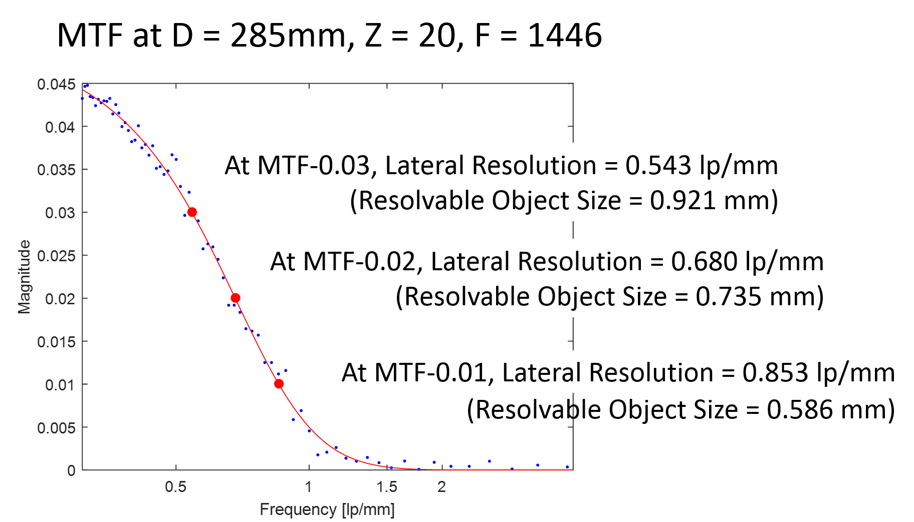
The lateral resolution evaluation is executed by mounting a target object consisting of 9 star targets in the field of view and then computing the modulation transfer function (MTF). The MTF resolution metric is defined as the image contrast with respect to frequency (f=S/2πR [lp/mm], where s is the number of sectors (a pair of black and white wedges) in a star target and R is the radius of a circle in the star target; lp/mm refers to ‘line pairs per millimeter’.
Figure 2 shows the acquired image of a star target,s image intensity along circles and the derived MTF at five radius values, Fourier transform of the image intensity, and its MTF.


 .
.
The depth resolution evaluation is conducted by mounting a target object consisting of a concentric circular pattern, rotating the target plane so that the points on the target pattern have gradual depth difference from the camera, and then computing the disparity for each point intersecting the concentric circles and a line passing the center of the circles. Figure 3 shows the acquired images and the disparity computation derived from the slope in the epipolar-plane image (EPI).

 and the reliability measure is the coherence of the slope estimation around a point.
Our preliminary results showed that the light field camera achieves lateral resolution in the range of 0.485-0.689 lp/mm. It was observed that, at MTF of 0.02 in the distance range of 285-985mm, the camera could resolve a depth difference less than 1 mm.
For interested parties, resolution evaluations of light field Lytro cameras are accessible interactivelly from here.